Volume 1 / Issue 2 / August 2014
Steam Systems - General
Heat transfer units that use steam to produce hot water are known as indirect heaters. They are often shell and tube type heat exchangers and are generally referred to as converters, hot water generators, and instantaneous heaters. The ASME Code for Unfired Pressure Vessels is the nationally recognized authority prescribing their construction for given temperatures and pressures. The term used varies with the heating medium and the manner of application. When these heaters use steam as the heat source they are usually called steam to water converters. In steam heated converters, the water to be heated circulates through the tubes and steam circulates in the shell surrounding the outside of the tubes. This results in condensate draining to the bottom of the heat exchanger shell as the steam gives up its latent heat (Figure 1).
![Figure 1 A typical steam to water heat exchanger system.]()
Figure 1 A typical steam to water heat exchanger system.
Steam to Water Heat Exchangers
The operation of the shell and tube heat exchanger is as follows. Steam enters the heat exchanger shell through the top vapor opening and surrounds the outside of the tubes. As energy is transferred through the tubes it heats the water inside the tubes. The heat transfer condenses steam inside the shell forming condensate that drops to the bottom of the heat exchanger shell. The condensate flows though the bottom condensate outlet and into a steam trap. The steam pressure in the heat exchanger shell has a direct correlation to the temperature of the condensate formed in the shell (Figure 1). The properties of saturated steam are such that the steam temperature varies with steam pressure (Table 1).
![Table 1 Properties of saturated steam.]()
Table 1 Properties of saturated steam.
When the latent heat of vaporization is removed, the resulting condensate will be close to the saturation temperature. Depending on the system load, slight sub-cooling may occur from the bottom of the heat exchanger and the inlet piping to the steam trap. The heat exchanger should be selected to operate at the minimum possible steam pressure. This allows the lowest possible condensate temperature to discharge from the steam trap and reduces the amount of flash steam in the return system. When heating fluids up to 200°F, the heat exchanger should be selected based on 2 psig steam pressure in the shell for the most efficient system operation. This may require a slightly larger heat exchanger than one operating at higher pressure; however it will result in a smaller less expensive low pressure steam trap and a smaller steam regulating valve. The low pressure selection will also limit the maximum temperature that can occur inside the tubes, should the temperature controller fail in an open position (Figure 2).
![Figure 2 Heat exchanger with modulating control valve.]()
Figure 2 Heat exchanger with modulating control valve.
It is standard practice to add a fouling factor in the heat exchanger selection. This fouling factor adds additional tube surface area to assure adequate heating after normal scale and corrosion deposits on the tube surfaces. A standard .0005 fouling factor will add 20 to 25% additional tube surface area. When the heat exchanger is new and the tubes are clean and shiny, the heat exchanger will operate at lower than design pressure even at full system load. For example, a new heat exchanger designed for 15 psi steam to heat water to 160 degrees will generally heat the full system load with 0 psi steam in the heat exchanger shell.
Heat Exchanger Selection
The heat exchanger should be selected for operation at the minimum pressure to provide the most efficient operation. The properties of saturated steam tables show a larger amount of the latent heat is available at low pressure. Less energy remains in the condensate reducing the flash steam losses. A reasonable guide would be to select a steam pressure that has a saturation temperature approximately 30°F higher than the required outlet temperature of the fluid being heated in the tubes. For fluid temperatures up to 200°F, 2 psig steam is recommended. (Table 1)
When a high steam pressure source is used, the pressure should be reduced by installing a steam pressure regulating valve or by using a combination temperature pressure regulator. After selecting the heat exchanger, the next step should be planning the installation. The heat exchanger should be mounted high enough to allow gravity drainage of the condensate from the steam trap into a vented gravity return line. If a gravity return line is not available, a condensate pump should be installed. The heat exchanger should be mounted with a pitch toward the condensate outlet. A minimum 1/2 inch pitch per 10 foot length should be provided. The heat exchanger should also be located such that removal of the tube bundle is possible.
Steam Traps
The steam trap must be capable of completely draining the condensate from the heat exchanger shell under all operating conditions. On a heat exchanger using a modulating temperature regulator to heat fluids under 212°F, the steam pressure in the shell can be 0 psig. To assure condensate drainage, the steam trap must be mounted below the heat exchanger outlet tapping and it must drain by gravity into a vented condensate return unit. When possible, the trap should be located 15 inches below the heat exchanger outlet. The 15 inches static head to the trap inlet will provide 1/2 psig static inlet pressure to the trap when the shell steam pressure is at 0 psig.
The trap should be sized based on this 1/2 psig differential pressure. A safety factor of 1.5 times the calculated full load capacity should be used to handle unusual start up loads. A float and thermostatic trap is normally the best selection for a heat exchanger. The thermostatic element quickly vents the air from the heat exchanger shell. The modulating float element provides continuous condensate drainage equal to the system condensing rate.
Failure to provide complete condensate drainage will lead to poor temperature control and possible water hammer. Any lift in the condensate return piping after the trap discharge requires a positive pressure to develop in the heat exchanger shell to provide condensate drainage. For this to occur, condensate must back up in the heat exchanger shell until enough tube surfaces are covered by condensate to build a positive steam pressure. When the positive steam pressure develops to move the condensate through the steam trap and up the vertical return line, over heating can occur on the tube side of the heat exchanger due to the positive steam pressure remaining in the shell. This results in a wide range of outlet fluid temperatures from the heat exchanger. A lift in the return line as shown above should be avoided on heat exchangers using a modulating control valve. A lift or back pressure in the steam trap return piping can flood the hat exchanger shell and cause severe water hammer as steam enters the flooded shell. The resulting water hammer can damage the steam trap, the steam regulating valve, the heat exchanger tubes and cause the gasket in the heat exchanger and trap to fail.
Trap Installation
The trap should be located below the heat exchanger shell to allow free flow o condensate into the trap. A strainer complete with a screen blow down valve should be installed ahead of the steam trap. A shut off valve should be provided in the trap discharge return line to isolate the unit for service. Unions should be provided to allow trap service or replacement. The return line from the trap discharge should be pitched into a vented condensate return unit.
Vacuum Breakers
Most steam to water heat exchangers provides a tapping in the shell to allow installation of a vacuum breaker. The vacuum breaker allows air to enter the shell when an induced vacuum occurs. Failure to install a vacuum breaker will allow the heat exchanger shell to operate at a negative pressure which may cause condensate to be held up in the shell. During light load, the heat exchanger will have a layer of steam at the top and air under the steam to provide just the right amount of heat. The vacuum breaker should be mounted on a vertical pipe 6” to 10” above the topping to provide a cooling leg. This protects the vacuum breaker from dirt and extreme temperatures.
Steam Regulator
The choice of the temperature regulating valve includes self contained temperature regulators, pilot operated regulators and pneumatic regulators. The steam inlet pressure to the regulator must be higher than the required heat exchanger operating pressure to allow flow. The available steam pressure should be at least two times the heat exchanger operating pressure to provide modulation of the regulator for good temperature control. This will also provide the smallest size steam regulator. The steam regulator should be sized based on the maximum lb./hr. of steam required by the heat exchanger. To properly size the regulator, the available inlet steam pressure and the heat exchanger design operating pressure must be known. The steam regulator should not be oversized. Over-sizing the regulator may cause the temperature to overshoot and the regulator will hunt more than a properly sized regulator. The steam regulator is normally smaller than the connecting inlet and outlet steam piping.
Regulator Installation
A steam drip trap should be installed in the steam piping ahead of all steam regulating valves. Failure to install a drip trap will allow condensate to collect in the steam piping ahead of the regulator. As the regulator opens, the mix of condensate and steam passing through the regulator may cause water hammer that can destroy the diaphragms or bellows used to operate the regulator. A steam strainer should also be installed ahead of the regulators to prevent dirt from entering the valve. Dirt can deposit on the valve seat and not allow it to close tight. The steam strainer should be installed with the screen pocket horizontally. Installation with the screen down, as commonly piped for water service, will allow a condensate pocket to form in the steam line.
This condensate pocket can carry into the main valve and cause water hammer or sluggish operation. Shut off valves, pressure gauges, a manual bypass and unions should be installed to allow proper servicing of the valves and strainers. When possible refer to the manufacturer’s installation manual for proper installation. The temperature sensing bulb should be installed as close as possible to the heat exchanger outlet. It is important that the full length of the temperature sensing bulb be inserted in the system piping. Any portion of the bulb installed in a no flow area will reduce the accuracy of temperature control. When the sensing bulb is installed in a separable well, heat transfer compound must be installed between the well and the sensing bulb to aid heat transfer. The tube side of the heat exchanger should have a continuous running recirculation pump to provide continuous flow past the sensing bulb. A minimum 20% recirculation should be provided. Pilot operated regulators with a pressure pilot require a downstream pressure sensing line. The pressure sensing line connection should be connected in a non-turbulent area downstream of the main valve; a minimum 10 pipe diameter downstream of the main valve is recommended. The steam pressure sensing connection can also be connected directly to the heat exchanger shell.
Condensate Coolers
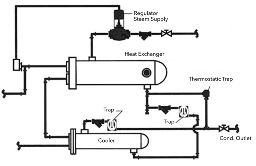
When heat exchangers operate at high pressure, consideration should be given to the addition of a condensate cooler. The justification will depend on the size of the heat exchanger and the actual number of hours per day the unit will be in operation. With a condensate cooler, the discharge from the steam trap on the steam heat exchanger outlet is piped through a water-to-water heat exchanger. A second trap is then installed on the discharge of the water-to-water heat exchanger to maintain saturation pressure and prevent flashing and water hammer from occurring in the condensate cooler. A separate thermostatic trap is installed to allow direct air venting of the steam heat exchanger into the vented return line downstream of the condensate cooler (Figure 3) .
![Figure 3 Installation with condensate cooler.]()
Figure 3 Installation with condensate cooler.
The water-to-water heat exchanger design differs from a steam heat exchanger. The water-to-water heat exchanger has internal baffles to direct the water flow across the tubes to improve heat transfer. Water-to-water heat exchangers are externally distinguishable as the shell inlet and outlet tapping’s are the same size; steam heat exchangers have a large vapor opening in the top of the shell and a smaller condensate outlet in the bottom. The fluid in the condensate cooler tubes may be the inlet water to the steam heat exchanger tubes. When the initial temperature of the fluid is too high to cool the condensate below 212°F, a separate fluid may be hated. Preheating domestic hot water or preheating boiler make up water are two possibilities.