Quantcast
Channel: Xylem Applied Water Systems - United StatesXylem Applied Water Systems – United States
Viewing all 273 articles
Browse latest View live

When a bucket trap is the wrong choice

$
0
0

Volume 4/ Issue 2/ July 2017

Although inverted bucket traps have a long history in the steam business and can stand up to demanding application, they’re not always the best choice — especially in a system with fluctuating loads.

Steam traps of any design must be able to perform these three functions:
1. Vent air from system so steam can enter.
2. Hold steam until its latent heat is removed.
3. Remove all condensate that forms when steam condensates.

Inverter bucket traps are good for steps 2 and 3, but they don’t vent air from a system quickly. That’s a problem with a changing load — for example, in a heating system where outside temperatures cause frequent cycling. When the system turns on, the load is heavy. As pipes and radiators warm up, the load is reduced. Every time the system turns off, steam condensate air rushes back to fill the vacuum. This air must be removed before steam can enter the system for the next cycle. Bucket traps just aren’t quick enough to handle this ongoing steam and condensate fluctuation.

Loads modulated by steam heat exchangers and air makeup coils with modulating control valves also work against the bucket trap. The control valve responds to load changes by changing system pressure, which affects the pressure differential across the trap. That changing pressure differential reduces the bucket trap’s capacity.

Remember, the bucket inside the trap is actually upside-down (hence, “inverted” bucket trap). This bucket has a specific weight for open/close operation. It is attached to the cover by a lever. At the other end of the lev is a plug, which is driven into seat of the trap when it closes. The trap is normally open, with the plug pulled down by the bucket’s weight. When steam starts flowing, it goes through a hole in the bucket. As more steam flows, the bucket become buoyant and the trap closes. Steam eventually condenses, the bucket loses its buoyance, and it falls, opening the seat. Condensate can drain through the seat to return piping.

To work correctly, bucket traps need to be primed with condensate. If the trap loses its prime, typically due to a low load, steam may bypass the bucket and flow directly into the return. The steam entering the trap will actually re-evaporate condensate inside the trap. Without any condensate in the trap, steam can easily pass through trap into the return line.

So what type of trap should be use in a modulating loads application?

A Float & Thermostatic (F&T) trap is the best choice for applications with modulating load. As the name implies this trap contains float and thermostatic element. The thermostatic element is design to vent large amount of air, and float can handle modulating load of condensate. These two conditions occur in every heating system and in every system with modulating steam load.

Hoffman Specialty offers many models of F&T traps:

Series H, C and X Steam Traps

For more information on steam traps, contact your local Hoffman Specialty representative. bellgossett.com/representatives

You can also visit our website at bellgossett.com/steam-specialties

Click here to download the 2017 July SteamTeam pdf

The post When a bucket trap is the wrong choice appeared first on Xylem Applied Water Systems - United States.


Specifying Tips: Vacuum Return Condensate Units

$
0
0

Volume 4/ Issue 2/ July 2017

Should you replace your vacuum return condensate system with a standard condensate return unit?

Before you decide, let’s look at what happens when a steam heating system starts up — a cycle that can happen many times a day, depending on the weather.

At startup on a two-pipe steam system, the steam mains, radiators and dry return lines are drained, and the entire system above the boiler’s water line contains air. Any steam added to the heating zone must push that air out of the mains and radiators, via air vent valves or thermostatic traps on each radiator and at the end of the steam main. Heating begins as steam replaces the vented air. Usually the radiator nearest to where the steam enters the building heats first. As air is vented along the steam main, additional radiators receive steam. Depending on steam main length and vent size, it may take five to 20 minutes for the system to vent and distribute heat throughout the building.

Attempts to improve the balance of heating in large single-zone heating systems included orifices to reduce steam flowing to radiators at the steam main’s supply end. In one-pipe systems, adjustable air vent valves were installed on steam radiators. While these methods helped, they could not adjust to different degree days, and the heating balance still suffered.

Vacuum systems overcome these difficulties, using a vacuum pump on the end of the return line to remove air from the system and maintain a 3” to 8” Hg vacuum. When the system is cold, the thermostatic traps are open, and air is removed from the radiators and supply lines. Removing air increases the differential between the positive pressure in the boiler and the sub-atmospheric pressure in the rest of the system. Steam flow is several times faster than in standard atmospheric systems, improving heat balance and speeding startup.

Other advantages include faster condensate return. That reduces surges caused by condensate holdup — which can cause frequent low-water cutoff at the boiler, and boiler flooding when large slugs of condensate suddenly return. Increased differential pressures across the system let designers reduce return pipe sizes, reducing upfront costs. The system can also use lift fittings and drain low wetted return lines without an additional condensate return pump in a pit.

When today’s building operators consider replacing vacuum pumps with standard vented condensate units, the engineer/contractor should point out these vacuum system advantages. If the system is removed, occupants on one side of the building may start opening windows due to excessive heat, while other occupants complain about being cold. Noisy returns may become an issue, because the smaller pipes of a vacuum system do not allow adequate condensate return on a vented system. Resulting holdup may lead to condensate surges that overwhelm the vented unit, dumping treated condensate down the drain instead of recovering it.

Increasing steam pressure or installing individual thermostatic radiator valves usually doesn’t work. The only way to eliminate the vacuum unit and maintain proper balance is to rezone the steam distribution lines. This requires additional thermostats, zone control valves and perhaps even a complete re-piping — often impractical and seldom cost-effective.

That leaves you to maintain the vacuum system. Piping must be tight. Thermostatic traps must be maintained to control returning condensate temperature — 160ºF for peak efficiency, with a maximum of 180ºF, since the system is under a vacuum and flash temperature of the boiler water is reduced. Higher temperatures or flash steam can cause cavitation in the pumps, shorten seal life and damage other components, resulting in expensive repairs. Proper trap maintenance is key to system balance and vacuum pump life expectancy.

Two types of vacuum units are typically seen on vacuum heating systems. The combination vacuum condensate pump creates the vacuum and provides the pumping pressure to return condensate to the boiler or to the feed unit, using the same pump for both functions. Other units use separate air removal and condensate pumps, which allow for individual sizing of air removal capacity and water transfer capacity (often needed in older systems to handle increased air leakage). The separate air pump also lets you use a temperature limit switch in the return line or the condensate tank to cut out the vacuum pumps when poor trap maintenance causes excessive condensate return temperatures. Some separate air removal and condensate pump systems can allow for this as the vacuum is not critical when the system is up to operating temperature.

Vacuum boiler feed systems are also useful for boiler conversions. New boilers often have considerably less water storage capacity; you need to install a boiler feed unit with a tank that can store condensate. With the vacuum pump installed on the feed unit, the condensate returns under vacuum directly to the feed tank. It is stored under vacuum until required by the boiler water level control.

Finally, note that eliminating your system’s vacuum return pumps will likely increase operating and fuel costs. A system designed for vacuum service includes pipes sized and located for vacuum service. In the end, it may simply be more practical to properly maintain the existing system and continue to operate under vacuum.

Click here to download the 2017 July SteamTeam pdf

The post Specifying Tips: Vacuum Return Condensate Units appeared first on Xylem Applied Water Systems - United States.

Goulds Water Technology donates state-of-the-art variable speed drive system to 2017 Empire Farm Days Show

$
0
0

Goulds Water Technology (GWT) is donating a variable speed drive system to the Empire Farm Days Show in Seneca Falls, New York, Aug. 8 to 10. Welcoming over 60,000 attendees and attracting nearly 600 exhibitors, the Empire Farm Days Show is the largest outdoor agricultural trade show in the Northeast.

The state-of-the-art GWT variable speed drive system — designed with a 150L15 submersible pump, motor and Aquavar SPD variable speed single pump drive — will pump water from an on-site well to irrigate the show grounds and supply water for farm demonstrations held throughout the show.

“Assembled and tested in Auburn, New York, our variable speed drive system can be used for a variety of farming needs, including irrigating crops and supplying water for livestock,” said Jeff Rook, Territory Manager – New York, GWT. “We are thrilled to donate the variable speed drive system to meet water needs for one of the largest trade shows in the farming and agricultural market, held just a short distance from our New York sites.”

The 2017 show marks the 84th anniversary of the event that began in 1931 as the Potato Field Days organized by the Empire State Potato Growers Association. In 1967, the event was renamed Empire Farm Days, and in 1988 Rodman Lott and Son Farms in Seneca Falls became the permanent host of the show.

More information about GWT’s variable speed drive system:

  • GWT L-Series Submersible Pumps: Designed for wells that are 6 inches or larger, the L-Series Submersible Pumps feature tungsten carbine bearings that provide superior shaft protection and prevent pump wear and a superior sand-handling design that ensures a longer pump life and fewer repairs. They also contain a built-in check valve that protects the pumps from water hammer and reverse water flow. The L-Series Submersible Pumps are NSF/ANSI 61 Annex G certified and comply with strict standards for safety and drinking water. To further ensure high quality performance and reliability, it is recommended that L-Series Submersible Pumps are paired with GWT 6” submersible motors.
  • Aquavar SPD Variable Speed Single Pump Drive: The single pump drive is designed to boost pump pressure for ground water and irrigation applications. It comes standard with dual phase input, which enables the drive to be used for three-phase and single-phase input. The pump drive also features a hand/auto option that allows the drive to run at full speed without a pressure transducer for longer periods of time. This is ideal for a new water well or system start up. It is preset for submersible or surface motor applications and can be ordered with or without a filter to efficiently meet the needs of a variety of submersible applications.

Connect with GWT on social media:

The post Goulds Water Technology donates state-of-the-art variable speed drive system to 2017 Empire Farm Days Show appeared first on Xylem Applied Water Systems - United States.

Maximizing Pump Performance for Submersible Wastewater Pumps

$
0
0

Presented by: Xylem Applied Water Systems

Download PDF

Motor design is key to the performance and service life of a pump. But determining the size of the motor required to drive the pump is something people often struggle with. This is especially true of wastewater submersible pumps. It’s a common assumption that you can use motor nameplate information at face value. That applies to some, but not all nameplate data. A primary example is service factor (SF).

Generally, service factor is the measurement used to determine the peak performance at which a pump motor can operate. The National Electrical Manufacturers Association (NEMA) defines service factor simply as a multiplier that indicates the amount of additional load a motor can handle above its nameplate horsepower. The service factor industry standard for a totally enclosed motor is 1.0.

To determine the service factor horsepower of a motor, multiply the nameplate horsepower by the service factor. For example, if a 1 HP motor has a service factor of 1.5, the motor’s service factor maximum horsepower is:

(1 HP) x (1.5 SF) = 1.5 HP

However, when sizing submersible wastewater pump motors, horsepower service factor, which applies only to the motor, is not a primary consideration. While service factor can be used to handle intermittent or occasional overloads, designers cannot rely on the service factor capability to carry the load on a continuous basis. Doing so will likely result in reduced motor speed, and the reduced life and efficiency of the pump.

Designing for continuous duty

When sizing a submersible wastewater pump motor, it’s important to consider whether the pump will ever be required to operate at a flow rate higher than the design point. If, for example, the pump was allowed to operate at the end of the head capacity curve, the actual horsepower requirement may exceed the design point selected motor horsepower and overload the motor. For this reason, it is common practice to size the motor not for the design point, but for the end of the curve or maximum horsepower requirements.

In the example above, a 7.5 HP motor would adequately power the pump at a design point of 120 GPM at 150 feet; however, looking at the end of the curve, brake horsepower requirements call for a 10 HP motor.

It’s also important to note that submersible wastewater pumps follow Affinity Laws – the mathematic relationships that allow for the estimation of changes in pump performance as a result of a change in one of the basic pump parameters. If either the speed or impeller diameter of a pump changes, you can approximate the resulting performance change using the following:

Pursuing peak pump performance

Taking all of these factors into account, the NOL Horsepower (or non-overloading brake horsepower) is a more accurate criterion when it comes to sizing the motor for a submersible pump. The NOL Horsepower is the maximum power value calculated in order to handle the maximum power demanded by the pump at any point along the curve. NOL Horsepower represents the amount of real horsepower going to the pump, not just the horsepower used by the motor.

Although not typically listed as part of the operational information on the pump nameplate, NOL Horsepower is one of the key factors confirmed during pump performance testing. If motors overload at any point on the published curves during testing, listing agencies like UL and CSA will not award product certification to the motor vendor.

While the factors used to size a motor that will operate anywhere on the pump curve may not be those typically used as defined for standard NEMA motors, there are advantages. Selecting a pump/motor combination that will function under all possible operating conditions will result in higher efficiency, longer service life and uninterrupted performance — even in a continuous duty application.

Bo Gell, Americas product manager, wastewater, has worked in Xylem’s Applied Water Systems business unit for six years. Gell has extensive experience in residential, commercial and marine pumps.

The post Maximizing Pump Performance for Submersible Wastewater Pumps appeared first on Xylem Applied Water Systems - United States.

Bell & Gossett awarded two CSE Product of the Year recognitions

$
0
0


Bell & Gossett awarded two CSE Product of the Year recognitions

Consulting-Specifying Engineer selects the fifth generation HYDROVAR and Technologic Intelligent Pump Controller for gold and silver awards

MORTON GROVE, ILL. — Sept. 14, 2017 — Xylem’s Bell & Gossett brand has received two Product of the Year awards from Consulting-Specifying Engineer magazine. The fifth generation HYDROVAR earned a gold award in the BAS/Controls/Energy Management category and the TECHNOLOGIC Intelligent Pump Controller earned a silver award in the Pumps/Pump Controls category.

Consulting-Specifying Engineer’s Product of the Year award is an annual reader’s choice contest that highlights the top new products in HVAC, fire/life safety, and electrical and plumbing systems engineering markets. Readers vote in as many categories for which they are qualified based on technological advancement, service to the industry and market impact.

“We are honored that the Consulting-Specifying Engineer audience has recognized Bell & Gossett for our product innovations and the advances our people and these system solutions are making on the industry,” said Mark Handzel, Vice President, Product Regulatory Affairs & Director, HVAC/Commercial Building Services Americas, AWS. “The fifth generation HYDROVAR and the TECHNOLOGIC Intelligent Pump Controller highlight our commitment to reducing costs and installation time for our customers while providing superior performance and energy savings.”

The fifth generation HYDROVAR was selected due to its ability to accurately adapt to a variety of system demands while maximizing pump performance and cost and energy savings. HYDROVAR features industry-leading multimaster functionality that enables each individual pump to take control of the system if one or more units or sensors are not active, reducing energy consumption of a pump by as much as 70 percent.

The TECHNOLOGIC Intelligent Pump Controller earned the silver award for its two advanced controller functions for hydronic HVAC systems ¾ the Start-Up Genie and an electronically controlled bypass ¾ engineered to reduce on-site setup and configuration time by more than 50 percent. These advanced controller functions help reduce operating costs, optimize building systems and ensure ease of service. Total set-up time with the Start-Up Genie is about 15 minutes, whereas most products today require 45 minutes for installation.

As winners, both HYDROVAR and TECHNOLOGIC will be highlighted in the September 2017 issue of Consulting-Specifying Engineer.

Follow Bell & Gossett on social media:

About Xylem

Xylem (XYL) is a leading global water technology company committed to developing innovative technology solutions to the world’s water challenges. The Company’s products and services move, treat, analyze, monitor and return water to the environment in public utility, industrial, residential and commercial building services, and agricultural settings.

With its October 2016 acquisition of Sensus, Xylem added smart metering, network technologies and advanced data analytics for water, gas and electric utilities to its portfolio of solutions. The combined Company’s nearly 16,000 employees bring broad applications expertise with a strong focus on identifying comprehensive, sustainable solutions. Headquartered in Rye Brook, New York, with 2015 revenue of $3.7 billion, Xylem does business in more than 150 countries through a number of market-leading product brands. The name Xylem is derived from classical Greek and is the tissue that transports water in plants, highlighting the engineering efficiency of our water-centric business by linking it with the best water transportation of all – that which occurs in nature. For more information, please visit us at www.xylem.com.

# # #

The post Bell & Gossett awarded two CSE Product of the Year recognitions appeared first on Xylem Applied Water Systems - United States.

Common residential wastewater myths demystified

$
0
0

Not everything that can go down the drain, should

Presented by: Xylem Applied Water Systems

Download PDF

The design and operation of residential wastewater systems can be a complicated and confusing subject for many, so it’s no surprise that more than a few myths exist. By addressing and debunking some of the most common misconceptions, professional contractors can better assist homeowners with the installation and maintenance of these essential water systems.

Myth 1: Bigger is better (when it comes to pump size) 

In most cases, bigger is not better when it comes to residential wastewater pumps. Whether a residential system requires an impeller or grinder pump, the pump should be sized for the application.

Although oversizing pumps is a common industry practice, it’s also an expensive and inefficient one. For example, oversizing the flow by 5 percent increases the pump’s energy demand by more than 15 percent, and an increased flow of 10 percent raises the energy consumption by 30 percent. An oversized pump will also short-cycle, turning on and off in rapid succession, which leads to premature pump failure.

A pump is considered oversized when it does not operate within 20 percent of its best efficiency point (BEP) on the pump curve. When a pump operates outside of this efficiency range, it increases the likelihood of cavitation — a noisy and damaging condition caused by vapor bubbles forming and collapsing at the pump impeller. Long-term mechanical damage to the pump can result when any of the following occur:

  • Increased vibration and noise
  • Suction recirculation
  • Reduced bearing life
  • Reduced shaft seal life
  • Shaft fatigue

Proper pump selection is a critical element in minimizing life-cycle costs and reducing energy consumption. By matching the equipment more precisely to actual system demands, pumps will use less power and require less maintenance, reducing costs and extending equipment life.

Myth 2: It’s wise to select a sump pump based solely on horsepower (HP) rating

Motor design is key to the performance and service life of a pump. But determining the size of the motor required to drive the pump is something people often struggle with.

For instance, the average homeowner may be aware that a 1/2 horsepower wastewater pump is a common pump size for a standard home because it can easily handle most applications. But what that homeowner may not realize is that all 1/2 HP pumps are not the same, and their output can vary from manufacturer to manufacturer.

The first step toward proper pump selection is to ensure that the required system flow and head fall on or marginally below the pump performance curve. Once the head capacity is established, the pump curve can be used to determine the horsepower — the amount of energy that must be supplied to operate the pump — required to meet the head and capacity requirements for the application.

It’s important to consider whether the pump will ever be required to operate at a flow rate higher than the design point. If, for example, the pump will operate at the end of the head capacity curve, the actual horsepower requirement may exceed the design point selected motor horsepower and overload the motor. For this reason, it’s critical to size the motor not for the design point, but for the end of the curve or maximum horsepower requirements.

The type of impeller — the moving element inside the pump volute, which drives the liquid — must also be taken into consideration as impeller size can greatly impact pump performance. For example, a vortex impeller might be preferred in a given situation because of its solid-handling capabilities, but the system might also require a higher HP rated pump. A pump performance curve shows the performance of a given pump with multiple size impellers. It is important for dealers and contractors to refer to the pump performance curve to identify the best, most efficient pump and impeller to select and install.

Goulds Water Technology (GWT), a Xylem brand, offers comprehensive in-person and virtual trainings on wastewater pumps and their applications through the GWT Factory School in Seneca Falls, New York, and its online e-Learning education platform. During the training seminars, water professionals learn how to select a wastewater pump, taking into consideration flow, system capacity, total dynamic head and other crucial calculations. They will also learn the advantages, disadvantages, features and applications of wastewater pumps and accessories.

Myth 3: All kitchen waste can go down the garbage disposal

Although people like to think there’s nothing garbage disposals can’t handle, that’s not the case. In fact, many common foods — and even some liquids — can clog garbage disposals and plumbing systems whether the blades can chew them up or not.

Buildups of fats, oils and grease present a significant challenge to residential and municipal wastewater pumping stations. Accumulations of these substances can clog the impeller, reducing pump efficiency or causing pump blockage. This can result in interruptions to operations and the need for costly maintenance. Obstruction by grease in particular is one of the most prevalent causes of force main backups and sewage overflows, costing the wastewater industry billions of dollars annually.

Seemingly harmless foods, like vegetables and pasta, can cause serious pump clogs, costing homeowners hundreds of dollars in repair. Below is a list of food that homeowners should not send down the garbage disposal.

  • Pasta and rice: These grains can bloat in the pipes and create significant clogs.
  • Stringy vegetables: Celery, rhubarb, asparagus, artichokes, chard, kale and lettuce are too stringy or fibrous to go down the disposal; they can easily wrap around the blade, clogging the drain.
  • Eggshells: The thin membrane on the inside of the shell can wrap itself around the blade of the disposal.
  • Coffee grounds: Though they appear to go down the drain just fine, coffee grounds can get stuck in garbage disposal traps. Over time, this can cause a system to clog.

Myth 4: Flushable wipes can easily travel through a sewage system

Flushable wipes might be a convenience, but that ease of use can come at a high cost as demonstrated in news reports about the detrimental effects these wipes can have on plumbing systems. It’s important to understand how these flushable wipes can cause system destruction and what pumps should be installed to better handle them.

The term “flushable” itself is somewhat misleading. Many consumers believe that when a wipe is labeled flushable, it is safe to flush it down the toilet. But, unlike toilet paper, wipes don’t disintegrate easily or quickly and can clog sewage treatment equipment and home septic systems. Clogging can occur when a number of wipes get stuck in the pump, or if debris builds up on the flushable wet wipes that are already stuck in the system.

Because of these potential harmful effects, flushable wipes need to be removed and dumped, often at the municipal level. They are removed using a large filter screen that is lifted by a hoist, or in a settling area that separates and removes the wipes by a front-end loader, since wipes don’t break down within the time frames for which sewage treatment plants are designed.

Myth 5: A grinder pump can handle anything

Installing a grinder pump is a common practice to alleviate pump clogs and sewer obstructions caused by wipes and other hygiene products that get flushed down the toilet.

Unlike a regular pump, which pumps out what flows in, a grinder pump is outfitted with steel blades that shred and macerate solids found in sewage into tiny bits. The liquid slurry is then pumped out to the central sewage system or septic tank.

While grinder pumps are a good choice if solids like flushable wipes are present in the wastewater stream, they are not a panacea. When materials like flushable wipes cause clogs, the only way to fix the plumbing issue is to remove them from the system. Grinders are effective in this situation only for clog prevention, not removal.

About the author: Bo Gell, Americas product manager, wastewater, has worked in Xylem’s Applied Water Systems business unit for six years. Gell has extensive experience in residential, commercial and marine pumps.

The post Common residential wastewater myths demystified appeared first on Xylem Applied Water Systems - United States.

Advantages of Wi-Fi control in residential well pumps

$
0
0

Remote monitoring provides valuable data to troubleshoot issues, avert downtime

Presented by: Xylem Applied Water Systems

Download PDF

Homeowners expect residential well pumps to keep up with everyday household water demands. But the endless loads of laundry, daily showers and regular dishwasher cycles often result in lower or inconsistent water pressure.

The advent of constant pressure systems in the residential market in recent years has largely alleviated homeowners’ water woes. These systems operate with a home’s well pump and a variable frequency drive controller to automatically monitor household water demand. The variable speed technology adjusts the speed of the pump to supply water as needed without any pressure fluctuations. The result is consistent water pressure — even when multiple water sources are operating at the same time.

Today, wireless monitoring technologies are further extending the performance and reliability of residential constant pressure systems. Mobile and remote offerings especially have become valuable tools, providing peace of mind to homeowners.

Although mobile monitoring is not a new concept for commercial and industrial grade pumps, the technology has only recently infiltrated the residential market. The main objective of Wi-Fi-enabled pump technology is to ensure optimal system performance. Real-time and historical data is collected to detect and troubleshoot potential issues to avoid system failures and costly repairs.

Mobile apps like Xylem Inc.’s AqWiFi act as a dedicated resource to provide remote monitoring of residential groundwater pumps and variable frequency drives (VFDs), such as Xylem brand CentriPro’s Aquavar SOLO 2. Using Wi-Fi connectivity, the app links the VFD to a laptop or a mobile device like a smartphone or tablet. Once connected, end users can wirelessly monitor the system’s performance and view the pump and motor status, as well as fault notification and history. End users can also view trends of critical parameters such as motor speed, motor current draw and input voltage.

Three major benefits of Wi-Fi-enabled residential pump technology are:

Greater accessibility: Residential well pumps and VFDs with wireless capability enable end users to monitor the equipment from a range of standard Wi-Fi-enabled devices anytime, anywhere. All of the pump’s data and settings can be accessed through the AqWiFi app installed on a mobile device or computer.

Better pump protection: The ability to monitor key system data in real time and access to fault history and system trends provides enhanced troubleshooting capabilities. End users can review the collected data, which may alert them to possible issues before damage is done to the well pump or the VFD.

Peace of mind: The ability to monitor residential well pumps and VFDs for system irregularities allows issues to be rectified quickly, minimizing downtime.

Homeowners rely on a consistent supply of water — even a few hours without it is a major inconvenience. Applying remote monitoring technology to residential well pumps helps keep equipment running smoothly — one less thing to worry about in busy households.

About the author: Chris Preston is a residential water product manager with expertise in submersible and jet pumps and residential pumping systems. For more than 10 years, he has worked for Xylem Inc. and its Goulds Water Technology brand as a product design engineer and project manager on multiple global new product development projects. Preston holds a bachelor of science degree in mechanical engineering from Clarkson University.

The post Advantages of Wi-Fi control in residential well pumps appeared first on Xylem Applied Water Systems - United States.

Goulds Water Technology introduces vortex wastewater pump

$
0
0

Download PDF

Goulds Water Technology (GWT), a Xylem brand, has released its VTX Series, a line of submersible vortex pumps that combines Goulds Water Technology’s reputation for reliability with an improved impeller design for superior waste-handling capabilities.

A recessed vortex impeller creates a whirlpool of pressure that pulls solids through the system without touching the vanes of theimpeller, minimizing clogging and easily allowing fibrous materials to pass through the system. Materials such as flushable products can pose clogging issues for wastewater systems due to their stringy, clothlike composition, collecting on the impeller and eventually clogging a system.

The vortex impeller of the VTX Series resists clogging more effectively than a traditional two-vane impeller and is capable of handling solids up to 2 inches in diameter.

Additional VTX Series features and benefits

  • Field serviceable — With the oil-free dry cap feature, a repair technician can service the capacitator in the field by simply pulling the pump from the pit and accessing the dry cap compartment, saving time and money on service calls.
  • PSC motor — The single-phase motor eliminates the need for a starting switch, and provides maximum starting torque and energy efficiency, for quick start-up.
  • Overload protection — Features built-in overload with automatic reset and is oil filled for constant heat dissipation and cool operation for continuous operation and extended product life.
  • Durable materials — The impeller and casing are cast iron and the shaft and fasteners are corrosion-resistant 300 series stainless steel; mechanical seals of silicon carbide provide superior abrasive resistance.

The VTX Series is available in five models, ranging from 1/2 horsepower to 2 horsepower, and displays pumping capabilities up to 208 gallons per minute.

For more information on the VTX Series, please visit goulds.com/vortex.

Connect with GWT on social media:

The post Goulds Water Technology introduces vortex wastewater pump appeared first on Xylem Applied Water Systems - United States.


Students develop human-powered pumps in Xylem-sponsored challenge

$
0
0

High school teams build and design irrigation pumps to benefit small-scale farmers


Rochester, NY – Oct. 19, 2017 – Four high school engineering teams (Victor High School, McQuaid Jesuit High School, Honeoye 4-H Robotics Team and Honeoye Falls-Lima High School) were recognized at the Let’s Solve Water Challenge on Oct. 14 for their innovative and efficient water pump designs. Nine FIRST (For Inspiration and Recognition of Science and Technology) teams competed for four prizes in the sixth annual contest sponsored by Xylem Inc., a global water technology leader.

The focus of this year’s challenge was to design and build a portable irrigation pump for small-scale farmers who grow their own food. Many parts of the world do not have access to electricity to power modern irrigation systems.

“Global water issues are important to our business, and we recognize that we must work to address them in a strategic, sustainable and responsible way,” said Ken Napolitano, President, Xylem’s Applied Water Systems business unit. “These students are the future of engineering; the Let’s Solve Water Challenge educates them on critical water needs worldwide and gives them a chance to apply real-world water engineering skills.

The annual competition was held at McQuaid Jesuit High School in Rochester, New York, the program’s primary advocate and competition host. Students were challenged to build their pumps with as much recycled/on-hand materials as possible. Students used their engineering skills to manage design constraints and build a product that:

  • Must prime and deliver water with no outside assistance
  • Delivers 2 gallons of water within a five-minute time limit
  • Fits into a 3-foot-by-3-foot-by-3-foot box with only a single stabilization handle allowed to exceed the vertical restriction
  • Can be held by a team member to collect weight

As part of the final competition, each team presented their working pumps and described their development process to a panel of judges that included the following Xylem mentors: Chris Felix, Mechanical Engineer; Paul Ruzicka, Global COE for Residential, Commercial and Waste Water and Chief Engineer; Luca Scollo, Mechanical Engineering Co-op.

Each team was evaluated by the panel of judges on design, time, exertion and pressure, and was awarded prizes totaling $4,000 based on four categories. The winners of this year’s Let’s Solve Water Challenge are:

  • Most elegant design/appearance/presentation: Devil Tech from Victor Senior High School, NY
  • Fastest time to fill up a 2-gallon bucket: SUITS from Honeoye 4-H Robotics Team, NY
  • Fastest prime: IgKNIGHTers from McQuaid Jesuit High School, NY
  • Overall weight (GPM per pound): Cougar Tech from Honeoye Falls-Lima High School, NY

“As a leading global water technology company, Xylem is focused on addressing the world’s most challenging water issues,” said Napolitano. “We’re excited to be involved in the Let’s Solve Water Challenge to enable the next generation of industry professionals to begin working today to solve tomorrow’s water-related issues.”

About Xylem

Xylem (XYL) is a leading global water technology company committed to developing innovative technology solutions to the world’s water challenges. The Company’s products and services move, treat, analyze, monitor and return water to the environment in public utility, industrial, residential and commercial building services, and agricultural settings. With its October 2016 acquisition of Sensus, Xylem added smart metering, network technologies and advanced data analytics for water, gas and electric utilities to its portfolio of solutions. The combined Company’s nearly 16,000 employees bring broad applications expertise with a strong focus on identifying comprehensive, sustainable solutions. Headquartered in Rye Brook, New York, with 2015 revenue of $3.7 billion, Xylem does business in more than 150 countries through a number of market-leading product brands.

The name Xylem is derived from classical Greek and is the tissue that transports water in plants, highlighting the engineering efficiency of our water-centric business by linking it with the best water transportation of all – that which occurs in nature. For more information, please visit us at www.xylem.com.

###

The post Students develop human-powered pumps in Xylem-sponsored challenge appeared first on Xylem Applied Water Systems - United States.

Updating old steam systems with a modern boiler feed unit? Don’t forget return lag time.

$
0
0

Volume 4/ Issue 3/ December 2017

A customer who recently installed a boiler feed unit was surprised to see a dramatic increase in makeup water use. Investigation showed the feed water was being lost through the unit’s overflow a few times a day. The customer called us to discuss, presuming the unit didn’t have enough storage. True, but far from the whole story.

It turned out the customer had replaced a very old boiler with one offering the same capacity. So far, so good. But as long as they were replacing the boiler and related piping, they also decided to abandon the system’s vacuum heating unit and install a new boiler feed unit. Their boiler guy, unaware of the abandoned vacuum unit, provided what the customer requested: a unit sized to the boiler. Uh-oh.

As you may recall from past newsletters, one benefit of vacuum heating units is increased differential pressure between the positive pressure of the boiler and the sub-atmospheric pressure in the unit’s condensate receiver. This increased differential moves steam through the system quickly; the steam doesn’t have to push air out of the way. The vacuum heating unit also allows for smaller pipes, located where you wouldn’t normally put them…like below grade. The vacuum can lift condensate out of wetted returns—but without the vacuum, that condensate returns only when the static pressure before wetted returns increases to a sufficient amount to push water through by the weight of the column of water.

So the building was taking longer to heat because of piping restrictions and lack of increased differential pressure. In turn, either the new boiler feed unit or the feeder on the boiler itself had to add water to keep the boiler steaming as the steam slowly made its way to the end of the system, condensed and came back. Plus, the new, modern boiler lacked the old boiler’s large water chest, since today’s higher-efficiency boilers use significantly less water.

In short, everyone missed a system sizing component. Boiler feed receivers should be sized to handle the condensate volume equal to the system lag time. Without the old vacuum, lag time increased. But once heat was established and the boiler shut down, all the extra makeup water was condensing and being returned. Since the boiler didn’t need more steam, the feed unit didn’t feed, and the extra makeup water from the beginning of cycle was being returned and running out the overflow to the drain. When the boiler started up again, so did the whole cycle.

Rather than taking things at face value and swapping an X# boiler horsepower boiler for a high-efficiency X# boiler horsepower boiler, the customer and provider should have looked at the entire system—keeping in mind the benefit lost when the vacuum unit was removed. You can determine system lag time by observing the actual time required for condensate to begin returning once the boiler has begun steaming. The system time lag volume is the amount of condensate developed by the system during the timed period. A five-minute storage is fairly typical for systems up to 200 BHP, or 6,900 lbs. per hour. Larger systems should have 10 minutes storage or more.

Remember also that system lag time is greater for a single-story building or a multi-building complex than for a single multiple-story building.

An undersized boiler feed receiver leads to condensate overflow upon system shutdown. Steam in the system condenses and returns to the receiver at this time. It’s best to retain this condensate; it contains heat and is as pure as distilled water. Therefore, size the receiver to contain the condensate without overflow. Oversizing the receiver won’t cause any system problems, but initial costs are higher. This is eventually offset by the preservation of condensate, reduced chemicals to treat the system, and less fresh water required for makeup.

Click here to download the December 2017 SteamTeam pdf file.

The post Updating old steam systems with a modern boiler feed unit? Don’t forget return lag time. appeared first on Xylem Applied Water Systems - United States.

Boiler maintenance can heat up your sales

$
0
0

Volume 4 / Issue 3/ December 2017

Funny how the people who change their smoke detector batteries every year and car oil every 3,000 miles let their boilers go year after year without even a thought of preventive maintenance. Then the boiler breaks down in the middle of winter, and you get an emergency phone call.

You can generate additional business, and help homeowners avoid unpleasant surprises, by offering boiler preventive maintenance service. Regular maintenance saves your customers money on fuel and replacement parts, and can also prevent potential hazards. Use the following “refresher” tips to create your own boiler maintenance program.

First, remember that hot water, steam, gas-fired, and oil-fired boilers each have special maintenance requirements. Oil-fired boilers in particular need more frequent inspection. Also, any boiler used to heat domestic water is operating year-round and should be inspected at least twice a year.

In general, a thorough boiler inspection/maintenance program involves checking:
• Fuel system – for proper operation, leaks and controls
• Combustion system – for boiler and exhaust leaks and signs of overheating
• Heating system – for leaks, uneven heating and zone balancing
• Circulator pump – for quiet operation
• Water – for cleanliness
• Gauges – for accuracy. Compare to a standard gauge.
• Expansion tanks – for proper pressure
• Controls – Follow the manufacturer’s recommended procedures
• Safety devices – Inspect safety relief valves, temperature and pressure controls, low water and flow-sensing devices

Manufacturers typically recommend specific procedures for inspecting their safety devices. Some general guidelines:

1. McDonnell & Miller low water cut-offs with self-cleaning probe should be removed and inspected and the probes cleaned or replaced every five years. Controls without self-cleaning probes should be checked every year.

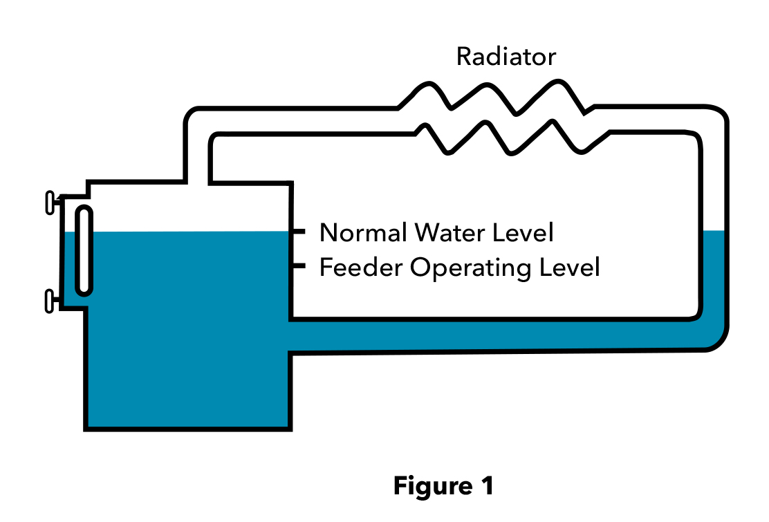
Series RB-24E Low Water Cut-off for residential hot water boiler with self-cleaning probe


2. Mechanical feeders – remove and clean the strainer and the cartridge. Replace if necessary.

247-2 Mechanical Feeder/LWCO combination


3. Float-type controls – inspect the float mechanism and clean. Replace if necessary.


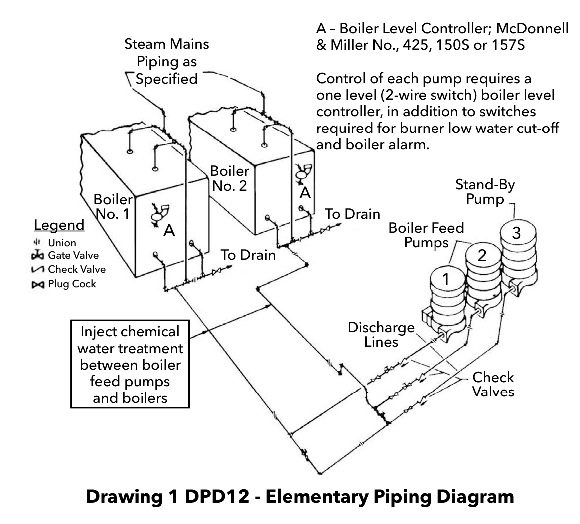
Series 150S LWCO-pump controller


4. Forced circulation copper boilers have flow switches in lieu of low water cut-off. Remove for inspection and clean every year. Check for deterioration of paddle and replace if necessary.


Series FS4-3 general purpose flow switch


Yes, it takes time and effort to remove and clean probes, floats, bellows or paddles, but if you skip this step, expect Saturday evening service calls. Inspect all controls and safety devices. Customers will appreciate your diligence when their boiler operates more efficiently and safely – and your business benefits, too.

For more information on boiler controls, or any steam or hot water heating questions, contact your local McDonnell & Miller Representative.

http://mcdonnellmiller.com/sales-service/

Click here to download the December 2017 SteamTeam pdf file.


The post Boiler maintenance can heat up your sales appeared first on Xylem Applied Water Systems - United States.

Bell & Gossett announces Parallel Sensorless Controller

$
0
0

Bell & Gossett announces Parallel Sensorless Controller
Building operators can maximize efficiency in up to eight pumps with intelligent technology

MORTON GROVE, ILL. – Jan. 22, 2018 – Xylem Inc.’s Bell & Gossett (B&G) brand is introducing its Parallel Sensorless Controller, a device that provides advanced system staging of up to eight pumps in parallel configuration to maximize system efficiency – an industry-leading offering with a large 5.7-inch touch screen that displays real-time feedback and enables energy modeling.

“Parallel pumping is a proven method of improving efficiency in pumping systems with higher control heads; the ability to control up to eight pumps with Bell & Gossett’s Parallel Sensorless Controller gives customers greater options in optimizing system efficiency,” said Jordan Ruff, Product Line Manager, Americas, Xylem AWS. “The B&G Parallel Sensorless Controller also replaces the need for a wired differential pressure transducer, reducing installation costs.”

Sensorless pump control technology relies on pump-specific algorithms, which can accurately predict where a pump operates on its curve. Using speed, torque and power data to know where the pump operates on the curve, sensorless pump controllers can be set up to take action based on those factors.

“Sensorless control is what drives the efficiency offering and optimization of B&G’s Parallel Sensorless Controller,” said Ruff. “B&G validates sensorless performance and customer hydraulic requirements at the factory to ensure precise and efficient operation in the field.”

The staging and destaging multi-pump configurations that are compatible with the Parallel Sensorless Controller are created on the basis of efficiency, thus allowing optimized hydraulic efficiency. It meets ASHRAE 90.1 system efficiency requirements and features advanced system staging with B&G’s expansive Efficiency Island operating range.

With the capability to run parallel configurations with up to eight pumps, B&G’s Parallel Sensorless Controller delivers the best efficiency staging to minimize energy costs and enables individual pumps to take control if one or more units or sensors are not active, ensuring reliable system flow and pressure.

Unique to the B&G Parallel Sensorless Controller is the real-time graphical display of the hydraulic pump curve, system curve and control curve. This enables the user to see actual system performance to confirm and adjust optimum hydraulic performance. The graphical display is also 40 percent larger than other models, providing better visibility of system data during commissioning and service.

The B&G Parallel Sensorless Controller integrates several other advanced features and functions to better control pump operation and provide critical information on pump efficiency and health, including:

  • Energy savings modeling, a predictive tool that compares energy savings against fixed-speed pumping
  • Standard communication protocols like BACnet and Modbus for seamless Building Management System integration, allowing for better control and monitoring of HVAC systems
  • A dedicated power supply so the system does not solely rely on variable frequency drive power
  • A dedicated and integrated disconnect switch that eliminates the need to install a separate switch, reducing costs and time.

For more information about Bell & Gossett’s Parallel Sensorless Controller, please visit http://bellgossett.com.

Follow Bell & Gossett on social media:

About Xylem
Xylem (XYL) is a leading global water technology company committed to developing innovative technology solutions to the world’s water challenges. The Company’s products and services move, treat, analyze, monitor and return water to the environment in public utility, industrial, residential and commercial building services, and agricultural settings. With its October 2016 acquisition of Sensus, Xylem added smart metering, network technologies and advanced data analytics for water, gas and electric utilities to its portfolio of solutions. The combined Company’s nearly 16,000 employees bring broad applications expertise with a strong focus on identifying comprehensive, sustainable solutions. Headquartered in Rye Brook, New York, with 2015 revenue of $3.7 billion, Xylem does business in more than 150 countries through a number of market-leading product brands. The name Xylem is derived from classical Greek and is the tissue that transports water in plants, highlighting the engineering efficiency of our water-centric business by linking it with the best water transportation of all – that which occurs in nature. For more information, please visit us at www.xylem.com.

The post Bell & Gossett announces Parallel Sensorless Controller appeared first on Xylem Applied Water Systems - United States.

Bell & Gossett expands capabilities of online system selection tool

$
0
0

Bell & Gossett expands capabilities of online system selection tool
New ESP-Systemwize functions aid engineers in selection process

Demonstrating its commitment to fostering greater efficiencies in hydronic system design, Xylem Bell & Gossett has expanded the capabilities of its one-of-a-kind ESP-Systemwize online selection tool that provides HVAC and plumbing system designers the ability to choose all system components within a single integrated tool.

Three new functions have been added to ESP-Systemwize — a variable speed option, floor space calculator and an operating expenditure (OPEX) estimator — providing engineers with valuable energy and cost-savings information.

“These new features help engineers select the best system based on project goals, saving them time on the job and increasing productivity,” said Rocio Echeverria, Vice President, Marketing, Americas Commercial Team, Xylem. “Regular updates with new features and capabilities will continue to ensure ESP-Systemwize is the most advanced online selection tool on the market.”

Introduced in 2017, ESP-Systemwize incorporates Bell & Gossett’s expansive product portfolio, applications expertise and hydronic systems knowledge, resulting in an intuitive, easy-to-use tool for selecting highly efficient pumps and compatible system accessories.

Constant or variable speed options
ESP-Systemwize now enables users to search pumps by constant or variable speed to discover and select products that will deliver optimal performance within a hydronic HVAC or plumbing system. Variable speed technology allows the pump to adjust operating speed and respond smoothly and efficiently to fluctuations in demand. By also using the ESP-Systemwize PLEV function — Bell & Gossett’s Part Load Efficiency Value criteria — system designers can gauge true pump performance by measuring the efficiency of the pump at partial flow rates.

Floor space calculator
With a growing focus on decreasing the size of mechanical rooms in commercial buildings to allow for more saleable space, engineers must identify the proper product and configuration to fit any mechanical room. ESP-Systemwize’s new floor space calculator takes the guesswork out of determining the need for vertical in-line pumps or base-mounted pumps. Providing engineering solutions that maximize square footage can help achieve overall project budget goals.

OPEX estimator
The cost of operations (OPEX) estimator helps identify energy and electrical costs associated with pumps and hydronic systems. Proper system design is critical to minimizing life-cycle costs and reducing a system’s power consumption.

ESP-Systemwize is readily accessible through the Bell & Gossett website or at esp-systemwize.com — no special user access is required. Advanced features are available to those who register, such as saving project schedules, generating submittals and sharing them with a Bell & Gossett manufacturer’s representative in their area. Other intuitive features of ESP-Systemwize designed to assist engineers in system design include:

  • Side-by-side product comparisons
  • Express select button narrows search
  • Searchable by groups of products
  • Analyze pump speeds in real time
  • Ability to choose pumps and accessories
  • Customizable project schedules
  • Warning system for potential selection problems
  • 24/7 technical assistance

For more information on ESP-Systemwize, visit www.esp-systemwize.com.

Follow Bell & Gossett on social media:

The post Bell & Gossett expands capabilities of online system selection tool appeared first on Xylem Applied Water Systems - United States.

Goulds Water Technology keeps a ‘field of dreams’ green

$
0
0

Goulds Water Technology keeps a ‘field of dreams’ green
Water irrigation solutions provided to the Travis Roy Foundation’s Wiffle Ball Park

Green fields and efficient sprinkler systems might not sound like a typical component in supporting spinal cord injury research and awareness, but for the Travis Roy Foundation, this was an important part of aiding its overall mission.

The Travis Roy Foundation hosts an annual Wiffle ball tournament in Essex, Vermont, to raise money for spinal cord injury research. For the three fields in this one-of-a-kind facility, the foundation needed a smart irrigation and pump control system to keep the fields green and lush. Goulds Water Technology (GWT) was selected to provide an efficient system to maintain the fields all season and has been delivering optimal performance since the installation.

The problem
The Wiffle ball park is comprised of three fields, each a to-scale replica of famous baseball parks including Wrigley Field, Fenway Park and the Field of Dreams. Little Wrigley, as it is affectionately named, features ivy and a chalk-style scoreboard. Little Fenway is complete with its very own green monster and mini CITGO sign in left field. Little Field of Dreams is meticulously surrounded by cornstalks.

“We host the tournament entirely on all three fields, and that’s a lot of ground to maintain and keep green,” said Pat O’Connor, Tournament Director. “I have been responsible for the fields for the past 17 years. It was very labor-intensive since I had to drag hoses around the field to properly water everything.”
In order to reduce the time spent on maintenance, O’Connor consulted with local well drilling, irrigation and lawn maintenance dealers and contractors to find a solution that was good for the field and enabled O’Connor to dedicate more time to other areas of the foundation.

The Solution
Spafford & Sons Water Wells in Jericho, Vermont, was selected to help lead the installation of the new sprinkler system and pump monitoring. The Spafford team installed a GWT Aquavar SOLO2 constant pressure system with a NEMA 3R enclosure and a 1.5HP 18GPM GS 4” submersible pump.

“We needed a system that would produce 70 psi to run water cannons as well as be on a pedestal outside,” said Jeff Williams, Vice President, Spafford & Sons Water Wells. “GWT provided the best system options. The fact that the irrigation contractor was also familiar with GWT really helped solidify our choice.”

The GS 4” submersible pump features stainless steel construction for convenient serviceability and industry leading hydraulic performance, which is needed to reach all three fields, and allows for convenient serviceability so Williams and his team can address potential issues easily.

“By coupling the GS pump with the Aquavar SOLO2, we are able to help ensure constant pressure control and monitoring to optimize performance of the entire system,” said Chris Preston, Residential Water Product Manager, Xylem AWS. “This system solution efficiently provides water that the fields need and helps maintain their high quality.”

Summary
In its 16-year history, the Travis Roy Foundation has raised more than $4.6 million for spinal cord injury research and grants. With the new GWT pump system, the Wiffle ball park is in top shape all season, not just when the area receives sufficient rainfall. This allows the Travis Roy Foundation to focus on increasing participation in tournaments and advocacy for spinal cord injury research.

The post Goulds Water Technology keeps a ‘field of dreams’ green appeared first on Xylem Applied Water Systems - United States.

What is the normal water line in a steam boiler?

$
0
0

Volume 5/ Issue 1/ May 2018

All boiler manufacturers identify the “normal water line” in their instruction manuals. It is typically denoted as “NWL,” and describes the height in inches from the bottom of the boiler upto this line. By not paying attention to the NWL, you can set yourself up for a whole lot of headaches. Manufacturers today know that, for their boilers to provide good “dry” steam, they have to rely on the near-boiler piping to help shake out any water that has come out of the boiler with the steam.

Most manufacturers list the height of the boiler’s heading as at least 24”, above the normal water line, because:

1) they want to minimize the amount of water that can climb up the supply riser(s) with the high velocity steam that is leaving the boiler, and

2) as the equalizer drip line fills with water on start-up because steam is condensing in the near-boiler piping, they don’t want this water to back up into the header piping. If this happens, the header piping’s internal diameter is drastically reduced, which immediately increases the steam’s velocity, and that can cause more problems.

The higher velocity steam will literally suck additional water right up out of the boiler and out to the system. This water-laden steam will condense prematurely because the water will rob the latent heat from the steam, causing uneven distribution of heat throughout the building. It will cause the steam vents to spit condensate. It will create water hammer because condensate will slam into elbows, tees and anything else in its way. It will also create a low water condition back in the boiler because so much water left the boiler prematurely. The only time the water level is the normal water line is when the boiler is off and cold. (Figure 1)

NORMAL WATER LEVEL is only normal when the boiler is off and cold.

As soon as the boiler starts to make steam, the water line has to change because some of the water is changing state from a liquid to a gas. (Figure 2) How fast the water changes into steam is a function of the boiler’s BTU /H capacity. An easy rule of thumb when attempting to calculate the boiler’s steaming rate is 0.5 GPM for every 1,000 square feet of equivalent direct radiation (EDR). This means water is being taken out of the boiler in the form of steam, at a rate of 0.5 GPM for every 1,000 square foot rating of the boiler. If you have a residential steam boiler capable of providing 500 square feet of steam, water is leaving the boiler at a rate of 1/4 GPM for every minute the boiler is firing. If a boiler firing cycle lasts 15 minutes and the condensate hasn’t started to return, 3.75 gallons of water will have left the boiler. That is a substantial amount of water that is no longer in the boiler.

We know how the NWL is established, but how it is set in a boiler? The only way to set the proper water level is by manually filling the boiler to the proper level. Some believe that an automatic water feeder is responsible for maintaining this water line, but a feeder’s only function is to maintain a safe minimum water level, working in conjunction with the low water cut-off. You don’t want customers thinking that an automatic water feeder is a convenience item, lest they forget about the importance of regularly checking their boilers.

If you have any questions about low water cut-offs, automatic water feeders and steam boilers, contact your local McDonnell & Miller representative. They are well trained on steam subjects.

Click here to download the May 2018 SteamTeam pdf file.

The post What is the normal water line in a steam boiler? appeared first on Xylem Applied Water Systems - United States.


Typical boiler feed unit discharge piping arrangements

$
0
0

Volume 5/ Issue 1/ May 2018

The following is a discussion of some of the more common discharge piping arrangements applied to boiler feed pumps. As previously discussed, use of a feed pump provides a reserve to feed the boiler, even when condensate is slow to return from the system. The economy of reusing treated water and feed water for its heat content is beneficial to the cost of operation, and reduces that amount of fresh water that needs to be added during heating cycles.

We will discuss five boiler feed piping arrangements that are adaptable to most low pressure boiler systems. Drawings are excerpted from the Section 190B document on our public website. 190B Bell & Gossett Domestic Boiler Feed Control

Drawing 1 DPD21-B below shows a single boiler with one pump for feed and a second pump for standby. Pump control for this arrangement is on the boiler, and is typically a single level of actuation for turning the pump on and off. Basic electrical control panels would typically include some type of starter or contactor with thermal overload protection to start the pump motors, and two auto-off-hand selector switches to determine which pump will be used as the feed pump.

Another version of the same drawing (the C version) indicates that customers can set the unit for automatic standby if two levels of pump actuation that can be dedicated to pump control are provided on the pump controller. In an automatic standby situation, the level in the boiler would recede and the first set of pump control contacts would close to energize the first pump. If that pump either could not keep up with the demand for water or failed to energize as the level continued to fall, the second set of pump start-stop contacts would close and the standby pump would be turned on to assist in restoring the boiler water level. The piping is the same; only the control on the boiler and panel wiring change.

Drawing 1DPD17 shows the addition of a second boiler. Pumps and boilers are cross connected so that either pump can feed either boiler. Pump control for this arrangement is on the boiler, and is typically a single level of actuation for turning each boiler’s pump on and off. Basic electrical control panels would typically include some type of starter or contactor with thermal overload protection for starting the pump motors, and two pump / boiler four-position selector switches. Selector switch number 1 would be for boiler number 1 and would be wired for off-hand-pump-1-pump-2. Selector switch number 2 would be for boiler number 2 and would be wired for off-hand-pump-2-pump-1. Thus, by opening and closing manual valves between the pumps and boilers and setting the selector switches appropriately, either pump can feed either boiler.

Drawing 1 DPD08-A shows two boilers with an automatic standby arrangement. In this arrangement, either pump can feed a boiler, with flow being directed to the respective boiler through some type of motorized, solenoid or proportioning valve. Pay special attention to the fact that, in this arrangement. each pump is sized for the total load of both boilers. Pump control for this arrangement is on the boiler, and is typically a two-level control. It typically controls the motorized valve, opening the valve to feed water into the appropriate boiler when the level in that boiler drops. An auxiliary switch associated with the motorized valve closes contacts to start a pump. If the level is restored in the boiler, the control will open, the motorized valve will close, and the auxiliary switch related to the valve will open and disengage the pump. If the level continues to fall in the boiler, the second set of pump control contacts will energize, starting the second pump.

Drawing 1 DPD12 below shows two boilers. A third, dedicated standby pump has been added. In this instance, each pump is sized for the load of its respective boiler. If the two boilers are not identical in size, the standby pump is sized for the larger of the two boilers. Pump 3 is the dedicated standby pump, and can be connected to either boiler by opening and closing manual valves between the pump and the boilers. The typical pump control for this arrangement would be a single level of actuation on the boiler for pump control. Basic electrical control panels would typically include some type of starter or contactor with thermal overload protection to start the pump motors, and two pump / boiler four-position selector switches. Selector switch number 1 would be for boiler number 1 and would be wired for off-hand-pump-1-pump-3. Selector switch number 2 would be for boiler number 2 and would be wired for off-hand-pump-2-pump-3.

An automatic standby version of this drawing is also available in the 190B document linked at the beginning of this discussion. Automatic standby would require two levels of pump actuation, and motorized valves of some type between pump 3 and both boilers in order to direct the flow to the boiler needing water.

It is important to note that automatic standby selections always require two levels of dedicated pump control, and in many cases auxiliary switches or relays to start the second pump automatically. As systems become more and more automated and more complex – adding additional boilers or changing alternation to an automatic style, for instance – additional ancillary items in the control panel are required that can complicate system operation and drive up costs dramatically.

When designing or replacing feed systems, and completing selections using the factory selection software, remember that feed units require the completion of the boiler feed questionnaire. A manual version is shown on page 2 of the 190B document. The factory needs to know the number of pump control signals to be used. This is different from how many are on the control.

For example, a manual system that has a M&M 150S controller for pump control has two levels on the control, but only one is needed for the pump. The second level in the case of the manual system can be used for some other appropriate function. This, however, does not negate ASME CSD1-1 safety codes that indicate there should always be two low water cut-offs on a steam boiler. In the case of the manual system, you might opt to use the second level of the M&M two-level control for the pump to actuate alarm or burner cut-off. But there must be a separate and independent low water cut-off as well. In automatic systems where both levels of actuation are used, there must be two additional low water cut-offs to protect the boiler. There is a strong case to be made in many of these instances to subscribe to the KIS method (i.e. Keep It Simple).

If you have any questions on feed pumping systems, contact your local Bell & Gossett representative.


Click here to download the May 2018 SteamTeam pdf file.

The post Typical boiler feed unit discharge piping arrangements appeared first on Xylem Applied Water Systems - United States.

L.A.’s Wilshire Grand Center stands tall with Bell & Gossett and A-C Fire

$
0
0

L.A.’s Wilshire Grand Center stands tall with Bell & Gossett and A-C Fire
High-efficiency HVAC and fire protection systems help project achieve sustainability and safety goals

When the Hotel Statler opened in downtown Los Angeles in 1952, it was the largest post-depression construction project in the United States. One of the major features of the $25 million project was that its 13 stories were “entirely air conditioned” — the pinnacle of a modern hotel in the early ’50s.

The Hotel Statler, later known as the Wilshire Grand, would become an L.A. cultural icon, hosting celebrities, politicians and businesspeople the world over. Yet, over time, its heating and cooling systems became so inefficient that not even a $20 million makeover could save the aging hotel, setting in motion the five-year construction of a new hotel, offices and retail space.

A 73-story glass and steel skyscraper now stands in the footprint of the old hotel; its distinctive rooftop spire making it the tallest building west of Chicago. The $1.35-billion Wilshire Grand Center opened in 2017 to international acclaim for its sophistication and luxury, a skyline-changing icon of modern design and a catalyst for L.A.’s economic rebirth.

The Wilshire Grand Center is also notable for achieving new levels of safety and sustainability, from its reinforced concrete core for earthquake and fire protection, to its radiant heating and cooling systems that use a fraction of the energy of a forced air system.

“The interdisciplinary collaboration among engineers, architects, mechanical contractors and others in the design-build process is resulting in new commercial buildings that maximize technology to better use materials and energy to improve the health and safety of occupants. Keeping costs in line and preserving resources for the future are intertwined in the process,” said Mark Handzel, Vice President, Product Regulatory Affairs, and Director, HVAC/Commercial Building Services Americas, Xylem AWS. “When you consider that half of the residential and commercial buildings that will exist in the United States in 2030 have yet to be built, the importance of this type of cooperation increases exponentially.”

In large-scale commercial building projects around the country, Xylem’s Bell & Gossett and A-C Fire Pump brands are integral to accomplishing energy goals through high-efficiency HVAC and plumbing system design, and ensuring the highest safety measures are in place for fire protection according to National Fire Protection Association (NFPA) 20 and local standards.

“Our technologically advanced and reliable system solutions paired with the expertise and superior customer service of our teams and our manufacturer’s representatives are why we are trusted partners in the design-build process,” Handzel said. “The Wilshire Grand Center presented numerous challenges for system design that met project goals while supporting a compact footprint.”

High-efficiency HVAC
Efficient use of energy within buildings is a primary focus of industry guidelines, such as ASHRAE 90.1, that have a direct impact on HVAC system design and installation. In addition, California’s Title 24 is a set of energy-efficiency rules that govern new building construction to improve water efficiency along with efficiency standards for mechanical systems. The Wilshire Grand Center design team, led by AC Martin Architects, worked with energy consultant Glumac to perform extensive energy modeling to design the glass façade, which informed the design of the HVAC and lighting systems — the two biggest energy users within a building.

With an HVAC system accounting for as much as 50 percent of a commercial building’s energy use, designing efficient heating and cooling systems was critical to meeting the project’s sustainability goals. Working with AC Martin and general contractor Turner Construction Co., ACCO Engineered Systems completed the design of the hydronic HVAC system that would achieve LEED Gold status. The HVAC system features a central plant with high-efficiency chillers and condensing boilers that supply chilled and hot water to the 2.1-million-square-foot building.

Relying on its longstanding relationship with Dawson Co., a Bell & Gossett manufacturer’s representative,

ACCO specified Bell & Gossett pumps and products for the Wilshire Grand’s HVAC system.

“A major challenge on the project was that construction had to begin prior to completion of the design — and the budget was already set,” said John Boncich, Senior Vice President, ACCO Engineered Systems. “We knew support from the Dawson and Bell & Gossett teams would be important from a technical standpoint and also in meeting critical milestone dates.”

Bell & Gossett’s role
The 1,100-foot-tall building is anchored by a seven-level podium structure that houses retail, restaurants, meeting rooms, ballrooms and a swimming pool. On top of the podium is 400,000 square feet of office space.

Bell & Gossett’s 300 psig working pressure VSX and e-1510 pumps supply chilled and hot water to the
podium and office levels, and standard working pressure VSX pumps serve the thermal energy storage system (TES) on the podium’s second level. The TES charges a large water tank overnight to reduce the number of chillers needed to operate the building during the day.

“Besides the versatility and robustness the VSX brings to a high-efficiency hydronic system, it’s easily serviceable and its compact design takes up less space in the pump room,” said Manuel Masso, Dawson Co. Vice President of Commercial Sales. “Decreasing the size of mechanical rooms means more saleable space, and that’s a priority in all commercial building projects.”

Bell & Gossett AHRI 400 certified plate and frame heat exchangers isolate the building’s pressure zones from each other. Other Bell & Gossett equipment for the HVAC system includes air separators and expansion tanks that increase and decrease pressures in the hydronic system in response to changes in building temperature.

The Intercontinental Los Angeles Downtown hotel, with about 900 rooms on floors 31 to 66, a 70th-floor sky lobby and bars and restaurants on floors 69 and 71, occupies the building’s tower structure. Inside the mechanical room on the 30th floor, 300 psig VSX pumps provide climate comfort to the hotel guest rooms via four pipe fan coil units and air handlers.

B&G Series e-90 inline pumps, designed specifically for commercial hydronic systems, provide radiant floor heating and cooling in the ground-floor lobby and in the sky lobbies.

A-C Fire Pump’s protection plan
From the rooftop’s open-air plaza on the 73rd floor, the views extend to the southern California coast 50 miles out. The roof design is one of the most talked-about features of the building, breaking with L.A.’s traditionally flat-roofed skyscrapers that are required to have helipads by city code. Wilshire Grand architects obtained an exemption from this 1970s rule reportedly because of the addition of other fire safety features that would exceed the city’s fire code requirements, such as the reinforced concrete central core that contains a staircase solely for the use of firefighters in the event of an emergency.

Stringent L.A. and California building codes for fire safety and NFPA 20 Standard for the Installation of Stationary Pumps for Fire Protection — as well as project parameters — drove the design process.

“One of the challenges was to design a system that met the city of L.A.’s requirement that total pressure shutoff can’t exceed 600 psi,” said Brian Buscher, Global Product Manager – Fire Protection, Xylem AWS. “Our A-C Fire Pump distributor, Starfire Inc., worked closely with sprinkler contractor XL Fire Protection on the design.”

Brian Callahan, President of XL Fire Protection, accredited Certified Fire Protection Specialist (CFPS) by NFPA and level 4 certified NICET designer, sketched out a two-zone system that met the requirements for the high rise, worked within the space restraints of the fire pump room, and did not exceed maximum pressure requirements.

“One pump services the low zone, but the high zone portion requires two pumps in series to create the 600 psi that was required. Once I knew the flow and pressure requirements, I was able to select the right combination of pumps to achieve that result,” said Starfire’s Paul Bennett.

A-C Fire Pump vertical turbine pumps and A-C Fire Pump 8200 Series horizontal split case pumps were selected for the job. Codes require an exact set of redundant fire pumps on each level, so that meant six fire pumps in total. “By getting the number of pumps down to six, there was no need for an additional emergency generator, saving project cost,” Callahan said.

Once the design was conceived, the team had to be sure the system would work as planned. “We had to do a lot of sizing and theoretical planning on what the pump curves would look like, especially in the high zone where the vertical turbines pump into the split case pumps and were approaching 600 psi,” Bennett said.

That also becomes more complicated because of NFPA 20 requirements for fire pump impellers, which state the pressure at shutoff cannot exceed 140 percent of the rated pressure at the rated flow and can’t be below 65 percent at 150 percent of the rated flow.

“One of the things we look at is not just the design point flow and head system needs, but also what the pressure is on the pump when it is at churn. We have to design the impeller to limit that pressure so that it is not overpressurizing the system components downstream of the pump,” Buscher said.

Even at shutoff, the static pressure in the turbine pumps was 77 psi, which required a pressure-reducing valve on the standpipe systems. “Controlling the pressure was our biggest challenge,” Callahan said.

The Wilshire Grand fire protection system design is also unique in the low zone pump room, with the vertical turbines sitting atop a 120,000-gallon three-story water tank in the second of five basement levels — with space at a premium on the site, there was no room for it outside the building. Designers had to be sure this setup would meet the NFPA 20 requirement on how tanks are constructed and that the fire pump would be capable of providing demand for the whole building in an emergency.

Beyond the build
In a project the size and scope of the Wilshire Grand Center, keeping to the timeline is vital to the project’s success. The construction site posed additional challenges — at just 2.8 acres, the site offered no space to store materials.

“A 73-story building takes years to build, so project coordination in regard to product lead times and deliveries had to be in line with the construction schedule,” Masso said. “Deliveries were lifted by cranes to the floors when they were needed.”

Once HVAC and fire protection systems were in place, the next steps were to test the systems and train building personnel on their operation.

On the fire protection side, the fire pump acceptance test was an essential step in obtaining the occupancy permit for the building. In testing the equipment, there was some fine-tuning in the time between turning on the pump and it feeding into the split case pump. By adjusting sequencing with the fire pump controller, the team was able to close the gap from 10 to 15 seconds at startup to just 7 seconds. The system also met the challenge of the 600 psi requirement.

“In the end, everything worked as designed,” Callahan said. “It’s not just putting in products; everything had to perform properly as a system and meet code.”

On the HVAC side, Dawson Co. conducted equipment training for maintenance and other personnel on the 18 Bell & Gossett products prior to the building opening. “It demonstrates the support that B&G brings to the table,” Masso said.

With nearly two-dozen skyscrapers being built in city of Los Angeles, Korean Airlines’ Wilshire Grand Center likely won’t be the tallest building in L.A. for long. However, from its roots as a pinnacle of modern design, it stands tall as a symbol of the new way of thinking about commercial building, using an integrated design approach involving the fields of architecture, engineering and construction to achieve safety, efficiency and sustainability goals.

The post L.A.’s Wilshire Grand Center stands tall with Bell & Gossett and A-C Fire appeared first on Xylem Applied Water Systems - United States.

Goulds Water Technology spearheads joint effort to restore clean water to North Carolina neighborhood

$
0
0

Efforts to provide safe water resources often are focused in developing countries, but the fact is nearly 2 million rural Americans do not have access to clean water.

Such was the case in the Holly Ridge neighborhood in Candler, North Carolina, located outside of Asheville. The subdivision was developed in 1990 in three phases with four wells serving 29 lots. Over the years, the well houses and well equipment fell into severe disrepair, and the 24 households served by these wells – including 45 adults and 18 children – were left with poor quality water or no water at all.

In January, Carol Gibson, president of the Holly Ridge homeowners association, contacted the Water Well Trust (WWT), a nonprofit arm of the Water Systems Council (WSC) established to provide wells for Americans who do not have a safe drinking water supply. Gibson told the WWT, “We can’t use the water to drink or cook. I don’t even like to bathe in it. It smells and it’s dirty.”

In response to the community’s water crisis, WWT’s Executive Director Margaret Martens and Susan O’Grady, Xylem Director of Marketing, Residential and Agriculture, joined forces to develop an effective and lasting solution for the subdivision’s water needs. Their combined industry experience and united cause gave rise to a plan that harnessed each organization’s resources for the largest project the WWT has undertaken to date. They enlisted local help from Merrill Drilling & Water Resources in Penrose and Hughes Supply in Statesville.

Although the Holly Ridge homeowners association had attempted to maintain the neighborhood well systems over the years, limited finances and knowledge thwarted proper upkeep. Upon inspection, it was discovered the wells did not have a filtering system and pipes were not properly insulated to prevent freezing during the winter. The practice of pouring bleach down the pipes to disinfect the systems further harmed well components and sediment build-up contributed to poor water quality.

“The homeowners attempted Band-Aid solutions over the last few years, purchasing pumps and tanks from retail stores that quickly failed because they weren’t meant to support that many houses and the setup wasn’t done properly,” O’Grady explained.

Because the Holly Ridge neighborhood is located in a remote, hilly area, hooking into the municipal water supply would have been difficult and cost-prohibitive for homeowners. Martens said the cost-savings to homeowners in rural areas who drill a new well versus hooking up to a municipal water supply is estimated to be as much as 85 percent.

Along with Xylem, Dustin Merrill, owner of Merrill Drilling & Water Resources, helped design and build the new water well systems. When water pressure issues proved complicated, Merrill and Chris Preston, Residential Water Product Manager, Xylem AWS, collaborated to troubleshoot system issues.

“Multiple trips were made to the job site to uncover issues and determine the best path forward,” said O’Grady.

In June, Merrill Drilling removed the existing water well systems, demolished the well houses and installed the new systems. Goulds Water Technology provided all of the materials for the project and supported the WWT with a $1,000 grant through Watermark, Xylem’s corporate citizenship program.

Two wells were outfitted with 18GP2020 ProPak pumps and Aquavar Solo2 VFD controllers and V350 holding tanks. A 7GP2020 ProPak pump and VFD controller was installed on a third well along with a 1,000 gallon buried potable water storage cistern. Crews also laid down more than 1,000 feet of new piping and 2,000 feet of new electrical wiring. Hughes Supply, a Goulds Water Technology distributor in Statesville, North Carolina, coordinated the transport of the donated pumps and controls to the job site.

Low well yield, which is typical of the Appalachian region, prompted the decision to install variable frequency drives (VFDs) and large holding tanks. Before the system was replaced, one of the Holly Ridge wells had been drilled nearly 600 feet deep, but only produced 2 gallons of water per minute.

“It will be much easier to keep up with pressure demands with the variable speed drives in place,” said Merrill.

In addition to consistent water pressure, the Aquavar Solo2 VFD controllers feature a dry well sensitivity setting, which detects dry well conditions and shuts down the system to prevent damage to the motor and pump.

“In the past, submersible pumps that may not have had dry well protection would fail if the well ran dry,” explained O’Grady. “In a dry well situation there is no water cooling the motor and excessive heat is generated causing failure.”

After the new well systems were installed, a group of volunteers from the Xylem office in Charlotte, North Carolina, partnered with Hughes Supply and Merrill Drilling in early July to build three new well houses through Xylem Watermark.

Thanks to these combined efforts, Holly Ridge residents have safe water again.

“Residents are grateful to be able to shower, to drink water and to bathe their children with clean water again,” said O’Grady.

The post Goulds Water Technology spearheads joint effort to restore clean water to North Carolina neighborhood appeared first on Xylem Applied Water Systems - United States.

Take control

$
0
0

Volume 5/ Issue 2/ August 2018

The core elements of a condensate handling unit include the collection tank, the pumps and the controls. Domestic Pump’s factory-built, tested and warrantied “Consolitrol” control panel helps these elements work in harmony and communicate effectively with users.

The “Consolitrol” panel handles an array of applications to power the pumps, configure the controls and communicate the status of the unit. It’s a valuable option that brings life and versatility to the unit. Here’s a look at all that it brings together.

Motor starters are required for any 3-phase power supply application, and with single-phase motors 3 HP and larger. A starter delivers safe, smooth startup as well as overload protection. Auxiliary contacts can be attached to the starters and wired to a building management system for remote “on” or “off” pump status indication.

Fused disconnects or circuit breakers protect the starters against power supply issues like short circuits. While fused disconnects are more budget-friendly up front, circuit breakers save money long-term, because there’s no cost for replacement fuses. The protectors are the points of power entry to the panel. Each pump or starter has its own protector; for a unit with two or more pumps, you can add an optional single point power connection.

Picture a typical unit with two pumps and the two dedicated disconnects with their handles on the outside of the control panel door. Those two handles are able to cut the power supply to the motors and the controls, making it safe to open the door and service the panel’s electrical parts, or the unit’s pumps and float switches. A power control switching relay makes it possible to keep the unit running while servicing just one of the two pumps. This relay is wired to both power supply paths that follow the disconnects. If the path that powers the controls is interrupted by its dedicated handle, the relay switches to the alternative power source and keeps the controls running.

Now let’s move from the power supply to the control loop. Code requires a power transformer when the power supply is more than 250 volts, and one is recommended when the supply exceeds 130 volts. The transformer delivers lower-voltage, single-phase power for delicate control options – such as pilot lights, float switches, alarms, alternators, selector switches, control relays, time meters, etc.

About those control options: Pilot lights on the control panel door indicate whether a pump is running. Float switches are generally a must – inserted into the unit’s condensate tank and wired to the control panel. They turn the pump on or off based on the tank’s water level, and can signal high or low level issues. Alarm options include buzzers, silencing relays, alarm lights, dry contacts for connection to remote building management systems – whatever combination is right for the customer. The optional alternator is available as either a double float switch (a “mechanical alternator”) inserted into the tank, or an electrical alternating relay mounted into the control panel. Its job is to change each pump’s lead-lag role for more even operation. Time meters track operating hours for each pump, a handy way to monitor servicing needs or calculate energy consumption. Selector switches let you manually set the pump’s operating mode – on or off, auto mode, lead or lag, continuously running, allocated to a certain signal from a dedicated boiler, etc. The type of selector switch depends on the unit type and features.


Domestic Hoffman Consolitrol Control Panel

Domestic Pump condensate handling units fall into two main categories – condensate return units and boiler feed units. Condensate return units are controlled by the water level in the tank; boiler feed units are controlled by the water level in a boiler. Control relays are essential for boiler feed units in scenarios such as multiboiler – multipump combinations with automatic pump standby; control of boiler feed valves; and communicating with the field.

Domestic Pump control panels are a hassle-free control solution for the condensate handling units. The panels are NEC and JIC compliant, and use IEC components of high quality, properly sized and wired to the application. The panels are available in various NEMA enclosures for indoor or outdoor application, NEMA2 being the standard. They can be unit or wall mounted. The most common control configurations are standardized. Customers can choose control options for their application, confident it will be the best fit. Any questions? Let us know.

Bozhidar “Boz” Ivanov
847-967-2622
e-mail: bozhidar.ivanov@xyleminc.com

Click here to download the August 2018 SteamTeam pdf file.

The post Take control appeared first on Xylem Applied Water Systems - United States.

Say “no” to suction strainers for condensate return and boiler feed units

$
0
0

Volume 5/ Issue 2/ August 2018

Condensate return and boiler feed unit specifications frequently call for a strainer to catch particles that could damage pumps. Basket strainers or “Y” strainers are equally effective, as long as they’re properly located and maintained.

Suction strainers, on the other hand, aren’t a good idea. They made sense in the 1920s and 30s, when the only pumps available to provide high pressure returns were turbines—whose close tolerance made fitted suction strainers a good choice to stop particle damage. But by the mid-1950s, several companies now within Xylem developed single- and multi-stage centrifugal pumps that could deliver higher pressures. These pumps have broader tolerances; solids up to 1/8” diameter can pass through the impeller of many Bell & Gossett pumps with no real harm.

Specifying engineers started to recommend the centrifugal design and multi-stage pumps for condensate return and boiler feed units. But old habits die hard; the engineers kept on specifying suction strainers. Let’s look at why that’s a problem – and how you can fix it.

The condensate unit is a tank, a pump, and float control at its simplest. If you put a suction strainer between the tank and the pump, the tank will fill, and the float control will turn the pump on. But if such a strainer is not maintained, it restricts water entering the pump. That starves the pump and maybe even runs it dry, damaging the seal.

You’ve also added a pressure drop between the tank and pump, across the strainer, reducing NPSHA to the pump. Now the pump’s NPSHR may exceed NPSHA—and the pump cavitates. So even if it doesn’t run dry, the pump is still damaged and the seal destroyed. This is especially likely when units are vented to atmosphere, and you’re dealing with hot condensate.

Plus, if the strainer hasn’t been maintained, it’s a good bet the system traps haven’t been maintained either. When they start to fail, the condensate returns even hotter, with even less NPSHA due to its temperature.

What’s the solution? Use a strainer, but move it to the inlet of the tank. The strainer still catches particles before they get to the pump, but now it also reduces sediment in the tank. If the strainer gets plugged, water doesn’t get into the tank, the float switch doesn’t rise to start the pump, and you don’t run the pump dry. If not enough condensate returns, a small system’s boiler shuts down, and a large system increases make up water into the feed unit—both signaling the need for maintenance.

In moving the strainer to the unit’s inlet, you may need to change the strainer type—especially where space is at a premium. A “Y” strainer may require back pullout space to remove and clean the strainer screen. Basket strainers don’t need back pullout space. Usually you can remove the lid or cover plate and lift the strainer screen out vertically. The strainer screen is somewhat self-cleaning, and the basket strainer usually has a large dirt pocket to collect system debris—especially useful for slower gravity returns. The bucket in which the strainer sits typically has a drain at the bottom. Just remove this and hose out system debris from the basket strainer body.

Larger systems with multiple zones might have a mix of pumped returns and gravity returns to the feed unit. If the designer has done the job right, pumped returns are sized for the pressure drop between the condensate and feed unit plus 5 to 10 psi, depending on the pressure drop. Flows entering the feed unit’s strainer at 5 to 10 psi will not create problems for the basket strainer. Remember, plugged strainers at the feed unit inlet will probably cause more make up water to be added to the feed unit or directly to the boiler. If you see an increase in use of make up water or treatment chemicals, it’s time for a system review. Higher energy bills are another indicator; make up water is colder and needs more energy to make it back to steam, increasing the bill to run the boiler. These indicators are all easy to monitor—and the solution is so simple. Clean the strainer.

An old joke about how specifications live forever starts by comparing the distance between train rails and going backward in time. The specification for the suction strainer is just such a case. In today’s steam systems with centrifugal style pumps, the answer is inlet basket strainers. If you’re writing the spec, update it. If you’re bidding on a spec that hasn’t been updated, take exception and quote the basket strainer—and include this article with your response. Giving specifying engineers this knowledge gives them the power to save money for everyone – including your customer.

Click here to download the August 2018 SteamTeam pdf file.

The post Say “no” to suction strainers for condensate return and boiler feed units appeared first on Xylem Applied Water Systems - United States.

Viewing all 273 articles
Browse latest View live


Latest Images